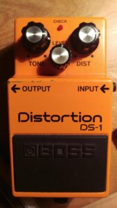
 The Boss DS-1 is:
1 – Cheap
2 – “Easy” to modify
3 – Not overly important to my rig.
So, it seemed like a good enough place to start for my first pedal modification. I was initially going to modify my dad’s CE-2, but after discovering that he has a rare version of it, I decided to go with a pedal that I could freely destroy.
I decided to go with a basic modification described at Reverb.com: Simple Boss Pedal Mods: Changing from Stock to Rock
I had some difficulties finding the exact components suggested by the article.
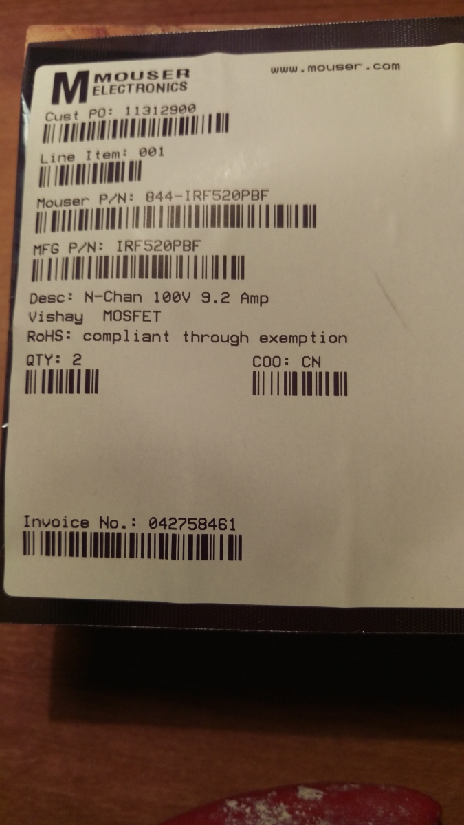 For the first stage, it suggests 2 IRF520 MOSFETs. Every IRF520 MOSFET I could find was listed as out of stock. All I could locate were IRF520PBFs. This is precisely the type of difference that will drive me nuts. Are IRF520PBF the same as IRF520? Are they close enough? Does it matter? What does PBF mean? (Turns out, it means lead free).
For the second stage, the article requests a “Polyester box capacitor, but a regular polyester capacitor would also work”. The only other specific on this I could find was in a caption of one of the photos that showed the author’s replacement capacitor as 0.022uf.
 I picked up the MOFSETs and a film capacitor from Mouser for $2.25. I spent more on the shipping than the components.
The mod appeared to be simple and the comments on the page seemed to indicate that a lot of folks have had success with it. I practiced de-soldering by disassembling a few TV remotes that we no longer use. I kept alternating between de-soldering wick and a pump to figure out which I had an easier time with. I’m still not sure which I prefer. What I ended up doing, was using the pump to pull the solder off initially. Once the component was removed, I used the wick to clean the remainder off the board before putting the new components in.
Before I did anything to the pedal, I recorded some samples of the unmodified DS-1 at various settings so that I could compare them later.
DS-1 Before Reverb.com Modification.
.jpg) I performed the mod out of sequence by starting stage 2 first. Changing the capacitor seemed like an easier introduction to the work and I could see no reason to do them in the suggested order. It took me a few attempts to remove enough solder to pull the original capacitor out. The new capacitor soldered in easily. When it was in place I hooked up the pedal briefly just to make sure that it was still generally functioning. I didn’t want to get to the end and wonder what step I broke it on.
I performed the mod out of sequence by starting stage 2 first. Changing the capacitor seemed like an easier introduction to the work and I could see no reason to do them in the suggested order. It took me a few attempts to remove enough solder to pull the original capacitor out. The new capacitor soldered in easily. When it was in place I hooked up the pedal briefly just to make sure that it was still generally functioning. I didn’t want to get to the end and wonder what step I broke it on.
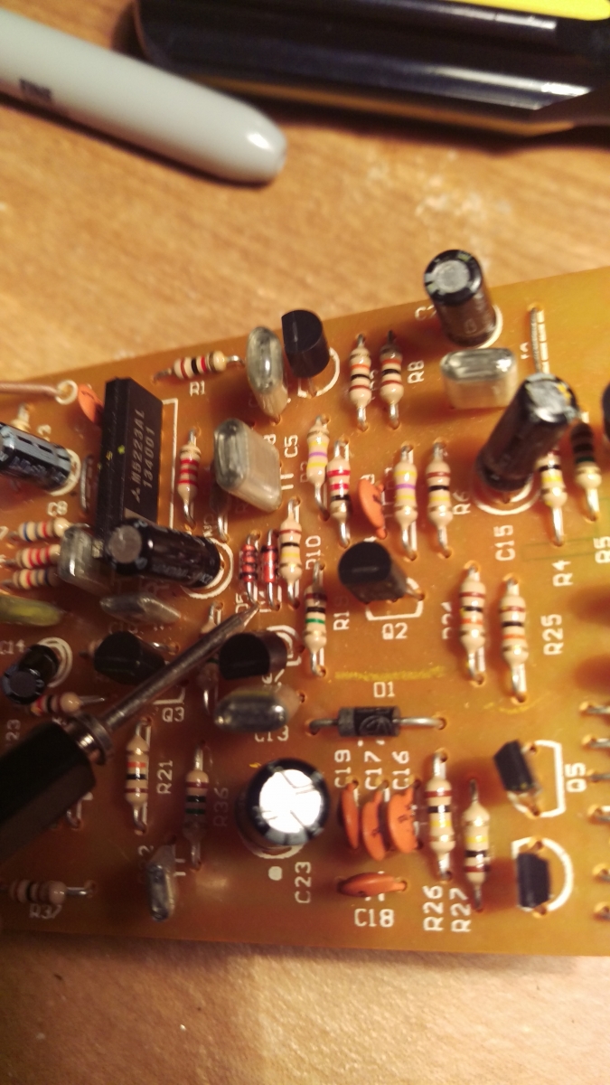 Replacing the capacitor gave me some confidence so I jumped into stage 1. Stage 1 was considerably more difficult and I was convinced at one point that I had destroyed my pedal. There is very little room where the diodes are on the board. They are very small and very close to other components on the board. It took me much longer to remove the solder from these and the pump seemed useless on these so I mostly stuck with the wick. I spent so long trying to get the diodes removed I was convinced that I had delivered too much heat to the board and damaged the pedal.
 The article stated that the MOSFETs had to face opposite directions but it didn’t matter which way they were oriented. The picture in the article shows that they author placed them back to back, but I opted to go front to front because it seemed safer to me not to have the metal portions of the MOSFETs facing each other. I don’t know if this actually matters or not.
Soldering the pins of the MOSFETs together was easy. Getting them to fit in the slots left open by the diodes was not. It seemed like I took the smallest components out of the pedal and replaced it with items larger than anything else in the pedal.
 The MOSFET pins are flat and were too wide to slide easily onto the board. I took some needle-nose pliers and tried to crimp the pins until they were not as flat and they would fit into the slots. Soldering the pins to the board wasn’t a simple task either. It seemed like the pin that was attached to the center pin took much longer to heat up enough for it to take solder. In an attempt to stop myself from applying heat to the board for too long, I got into the habit of counting out 5 seconds every time the iron touched the board. If I wasn’t done when I hit 5 I would remove the iron for a while before trying again. I wasn’t able to get the solder to take within the 5 seconds on the pins that were soldered together, so I turned up the temperature of the iron a bit. In hindsight, this was probably unnecessary since if the solder wasn’t melting that should mean that the component wasn’t hot enough for it.
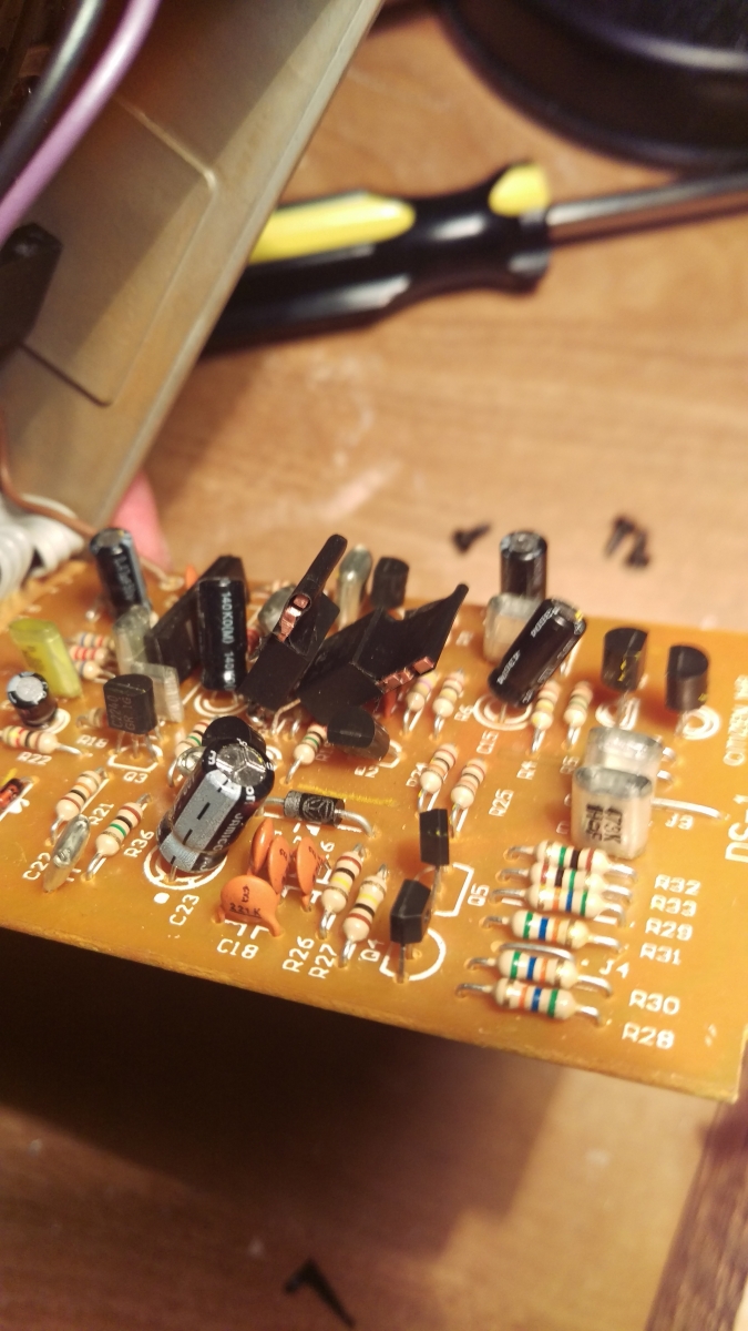 Once everything was in place, I hooked up the pedal before putting the case back together just to make sure that it was working and to my astonishment, it made sound. It even sounded like distortion. I put the case back together and when I hooked it up no sound would go through the pedal at all. Luckily, I had read in the comments of the original article that the MOSFETs are big enough that they can touch other items in the pedal when it is closed that could short it out. I took it back apart and put a small piece of electric tape on the top/back of each MOSFET (again, I don’t know if this matters or not) and then tested hooked the pedal up without the case again. To get it to work in the case, I went through a few iterations of pressing the board down as if the case was closed, seeing if the pedal worked, removing it, and bending the MOSFETs and a few other nearby components so that they would lay differently in the closed case. A picture in the article seems to suggest that the author laid the MOSFETs away from each other, but I had difficulty getting it to work in that arrangement. I ended up laying them in the same direction towards the back of the pedal. I was concerned bending the components around that I would break one of them but I didn’t.
Once I had the pedal back together and functioning, I recorded another sample of tones to compare against the original recording.
DS-1 After Reverb.com Modification.
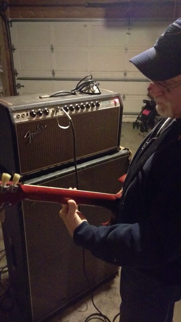
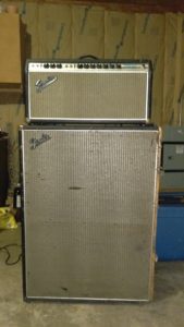
I have to say, this mod did improve the tonal quality of the pedal significantly. I was particularly surprised by how much lower the “level” setting needs to be with the updated components. The new distorion sound still has much more saturation than it probably needs, but tonally it is much fuller. In particular, I noticed that the updated pedal is much more responsive to harmonics than the original. Feel free to compare the videos above for yourself. I apologize for the buzz in them. Something in my house causes my amp to buzz and I haven’t been able to determine what it is.
There are a ton of mods for the DS-1 online. Now that I have a successful one behind me, I may try a few more.